With 2.4GHz Wi-Fi networks largely being considered legacy, wireless designs focusing only on 5GHz coverage are fast becoming the default. This is not really a new phenomenon, enterprise wireless design has been focused around 5GHz coverage for some years now, with secondary 2.4GHz coverage only for support of older devices. Today however, we see large venues and enterprises dropping support for 2.4GHz altogether. A number of manufacturers offer (and have for some time) the ability to configure an AP into dual-5GHz operation. Being able to change the (now unused) 2.4GHz radio into 5GHz mode provides additional 5GHz capacity without the need for additional APs. Today we examine some of the design options offered by dual-5GHz APs, along with some pros, cons, and caveats.
Of course, 2.4GHz is not going away just yet, while 2.4GHz did not really benefit from the introduction of 802.11ac back in 2013, many devices still use 2.4GHz-only chipsets today due to their reduced cost, and will likely continue to do so. Also, Wi-Fi 6 has attempted to breathe some new life into 2.4GHz with the introduction of enhancements like OFDMA and BSS Colouring. How Wi-Fi 6 will play out in the 2.4GHz band still remains to be seen.
Moving on to dual-5GHz design, there are a couple of points to discuss.
Note – some of the content here is specific to the European regulatory domain governed by ETSI.
Indoor coverage – External antennas
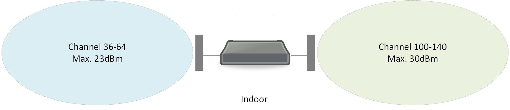
In the ETSI domain, all 5GHz channels (36-140) are permitted for use indoors, with different allowed EIRP for each band, 23dBm for channels 36-64, and 30dBm for channels 100-140, as shown in the image above. Unfortunately, unlike our friends in the US, in the EU we do not have useful access to the U-NII-3 band. Hopefully this will change soon, as it already has in the UK, for example.
From a design point of view, using two external antennas to cover different areas is extremely useful, as it allows for cost savings, doubling of 5GHz coverage while using only a single AP. One key consideration here is the difference in available Tx power between the two radios (or more accurately, sub-bands), i.e. 30dBm vs 23dBm, which needs to be factored in. Where this can become more of an issue is when the two coverage areas overlap, see image below.
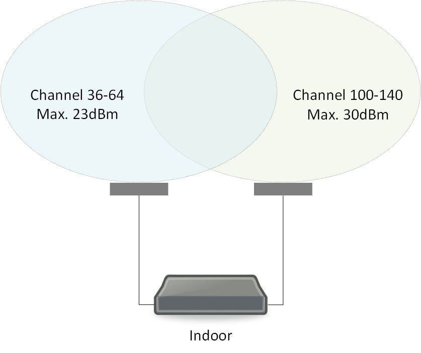
If, for whatever reason, the design requires 30dBm, it is important to remember that only one of the radios will be able to deliver that much power. RF profile configuration is usually mandatory with this type of solution to ensure that the output of the two antennas is balanced. Failing this, we could have a scenario where clients would tend to prefer the stronger of the two radios. The use of load balancing features is also a consideration with this type of design.
Outdoor coverage – External antennas
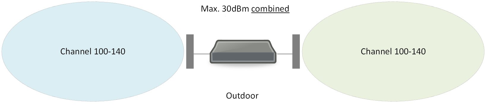
When applying dual 5GHz design to an outdoor environment we run into some regulatory challenges; in Europe, only channels 100-140 are permitted for outdoor use. In addition, there needs to be a 100MHz separation between channels (typically enforced by the WLC). For example, channel 100 is on a frequency of 5500MHz, adding 100MHz of separation makes the next available frequency 5620MHz, or channel 124. This obviously has a serious impact on channel planning.
The regulatory hassles don’t stop there, ETSI document EN 301 893 V2.1.1 of 2017 – “5 GHz RLAN Harmonised Standard covering the essential requirements of article 3.2 of Directive 2014/53/EU”, states:
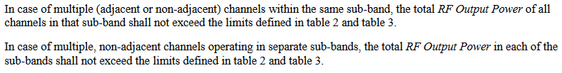
Meaning that, if we are using two channels from the 5470 to 5725 sub-band (which we need to do in this case), the maximum power of 30dBm applies to both of the radios combined. Below is the referenced table 2.
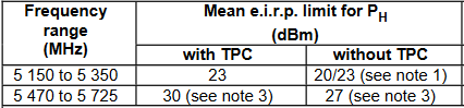
In practise this means that the available Tx power for each radio is reduced, as the maximum for each sub-band must be shared between the radios. Considering that the stated maximum is EIRP; in the case of two 13dBi antennas, we have a maximum configurable Tx power (at each AP) of just 2dBm. This may not be sufficient for every use case, actually it many outdoor use-cases it won’t be, making this type of solution better suited to low power requirements. Simply put, it may just be easier to stick with a single antenna per AP.
This issue goes away in countries where U-NII-3 channels are permitted outdoors, as we can use channels from each of the U-NII-2 and U-NII-3 bands per radio.
Micro Macro
Micro Macro design came about from the need to re-use 2.4GHz radios that may have been previously shut down, and relates to APs with internal antennas. The idea is that clients at a further distance from the AP will have reduced RSSI, and therefore reduced data rates. While clients that are closer to the AP will need to slow down to accommodate those clients transmitting from further away. By creating a second, smaller, Micro cell, the clients that are close to the AP can associate to the Micro cell and not be affected by the clients transmitting with lower data rates.
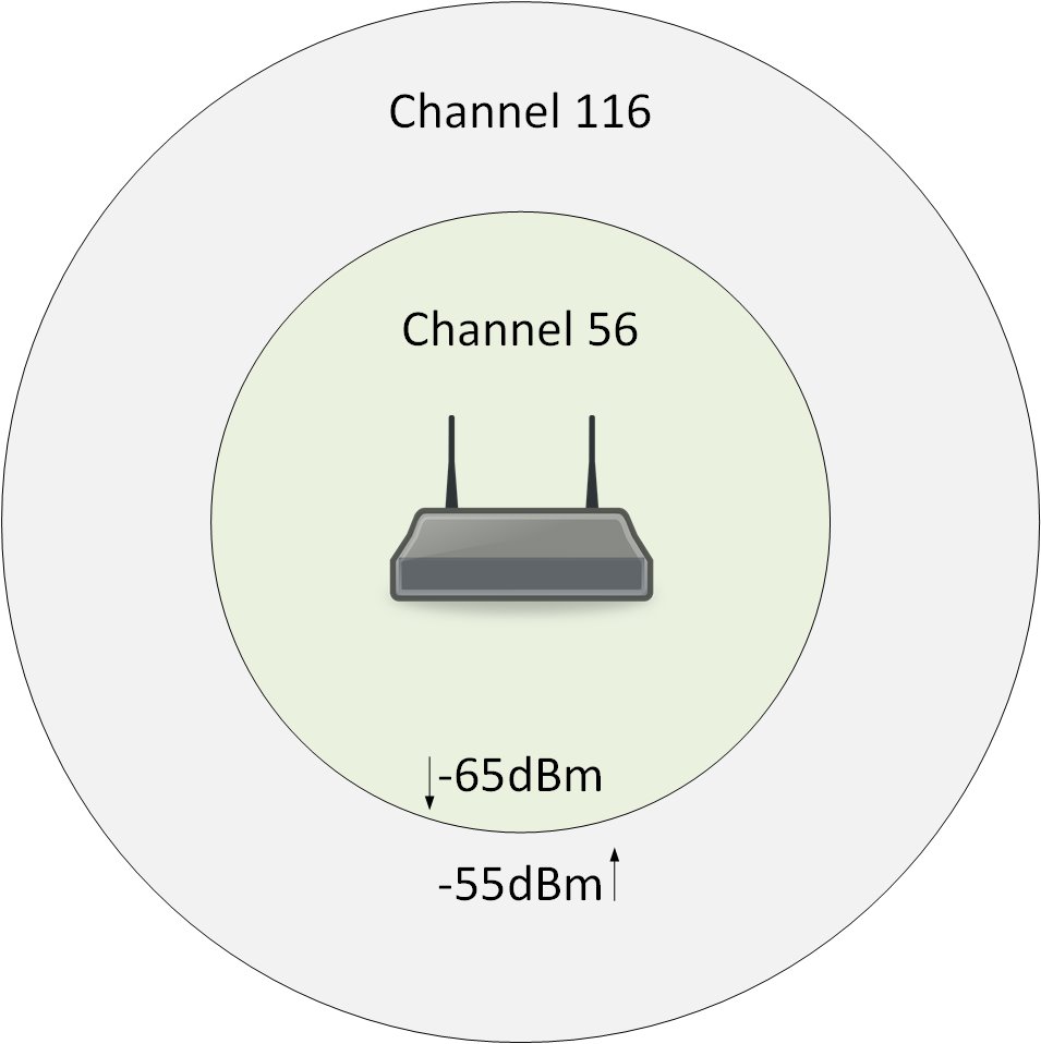
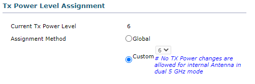
Here too, there are some considerations that need to be taken into account. Firstly, we still have the 100MHz separation requirement, although in this case it is less of a concern as internal APs supporting Micro Macro architecture tend to be installed indoors. Secondly, the power on one of the radios is significantly reduced, not due to regulatory requirements, but to limit the nearfield interference caused by two radios operating in the same band, inside the same AP. The power level on the second radio, the Micro cell, is limited to the lowest setting and is not configurable. Screenshot below from a Cisco WLC.
The last thing to consider for Micro Macro design, although it really applies to all the cases presented here, is how clients roam between the 5GHz cells. From a client point of view, each cell is nothing more than another BSSID, meaning that standard roaming rules apply. i.e. the client is still responsible for transitioning between the Micro and Macro cells, and all that can be done from the infrastructure side is to try to influence the client decision, typically through the implementation of 802.11v and/or 802.11k.
Going back to the image above depicting Micro Macro cells, Cisco APs have two (configurable) thresholds defined, set at -55dBm and -65 dBm by default. These thresholds are used to trigger an 802.11v BSS Transition Management Request by the AP. If the client is associated to the Macro cell, and the AP hears the client stronger than -55dBm, the AP suggests the client move to the Micro cell. Similarly, if the client is on the Micro cell, and heard by the AP below -65dBm, the AP suggests the client move to the Macro cell. In both cases the Neighbour Report in the BSS Transition Management Request contains only the BSSID corresponding to the other radio. The capture below demonstrates this.
As is the case for any other roaming event, unless additional features are enabled to actively disassociate the client, the client is not forced to honour the BSS Transition Management Request. Considering the potentially large difference in Tx power between the Micro and Macro cells, it is quite likely the client will hear the Macro cell at a higher RSSI, in this case roaming to the (potentially better performing) Micro cell may actually mean a reduction in received signal strength. This is somewhat counterintuitive, and whether the client accepts this or not is down to how much weight is put on the RSSI value within the client’s roaming algorithm. There is therefore a layer of complexity inherent in Micro Macro design which requires some additional planning, including making sure the clients play well with 802.11v.
Proprietary solutions can also be effective at steering clients to the intended cell, such as (Cisco) Probe Suppression where the AP can be configured to ignore client probe requests. By ignoring client probes the BSSID is effectively ‘hidden’ from the client.
This can be demonstrated using just a single 3802i AP with both radios operating in 5GHz. The capture snippet below shows probe suppression in operation.
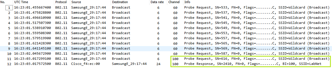
Channel 60 is the much-stronger Macro cell, and channel 100 is the Micro cell. We can see the AP is not responding to client probes on channel 60. As soon as the client probes on channel 100 the AP immediately sends a probe response advertising the SSID. In this example the client was right next to the AP, with the Macro cell being significantly (~20dBm) stronger.